 English
 中文
中文







Alumina Ceramic Isolator: Design the Path Before the Voltage Test
Sometimes, an insulation failure doesn't start with a flash of lightning.
It could begin as a barely noticeable tracking mark next to a hole or dust trapped in a groove or a metal washer rubbing on a cracked ceramic edge. It may appear fine at the time but at that time electrical separation will not be as reliable.
Design of an alumina ceramic insulator should thus be based on the way that electricity must travel, rather than simply on a material data sheet.
Clearly articulate What the Isolator Must Separate
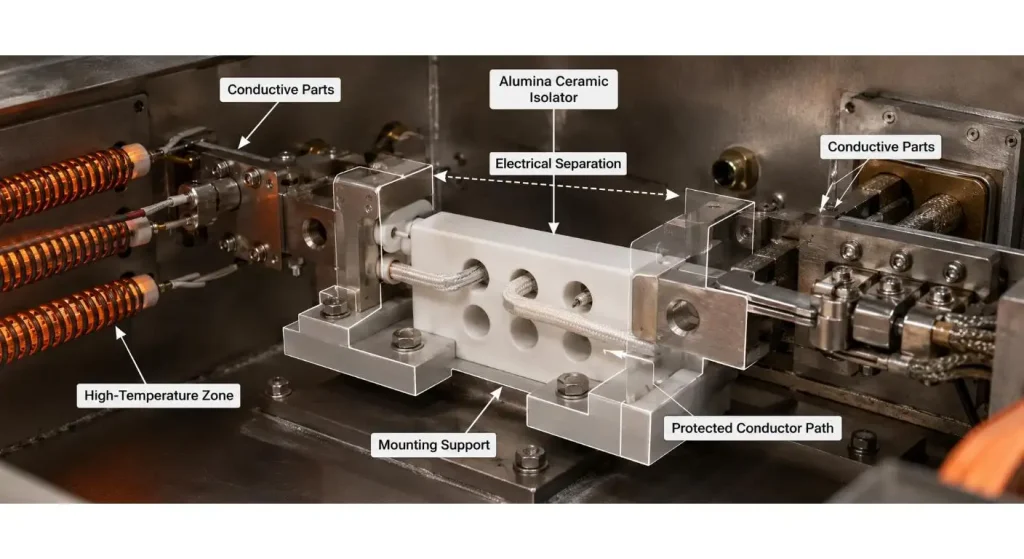
The first step is to determine the conductive components on both sides of the ceramic.
Verify the correct voltage, transient voltage if any, current of AC or DC, frequency, temperature and environment and whether it is necessary for the isolator to handle mechanical load as well. A part separating two terminals in a dry enclosure is required to perform a different task as compared to an electrode supporting part in proximity to heat, moisture or process residue.
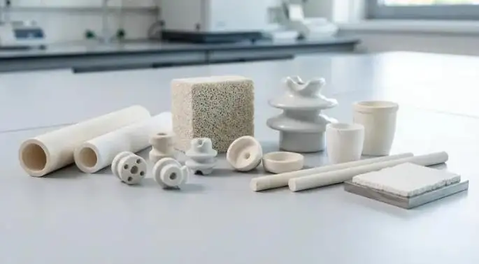
ProuPCERA's alumina ceramic insulator is available for electrical, heating, sensor and industrial use, such as multi-hole structures. The final geometry should still be based on the actual conductor configuration and mounting.
Bulk Insulation is One Barrier of Many
The complete assembly is not necessarily safe if the ceramic body has a high dielectric strength.
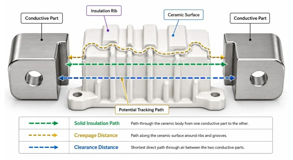
It is possible for electricity to be conducted through the air between conductors or along a contaminated ceramic surface. Clearance, creepage distance, ribs, grooves, humidity, dust and altitude may therefore be important, and as important as wall thickness.
IEC 60664-1 covers clearance and creepage distance and/or solid-insulation coordination for the low-voltage equipment to which it is applicable. These distances should be calculated from the system conditions, and not simply copied from another ceramic component that is unrelated to the problem at hand.
The insulation surface is formed with the ceramic. This surface length and protection or cleanliness will depend on the design of the equipment.
If you're using Multi-Hole Geometry, you will need a Conductor Map
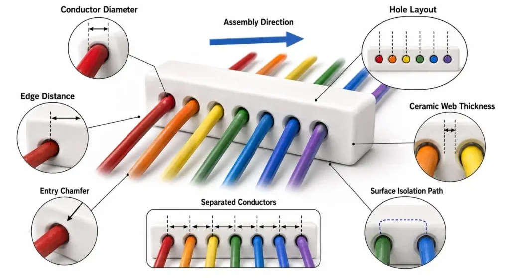
Multi-hole isolator is a type of isolator which can arrange several wires or electrodes into a small area. It can also be used to position conductors too near each other if it is thought of as a drilling exercise.
For each hole write:
- the conductor diameter;
- electrical potential;
- required separation;
- insertion direction;
- allowable movement;
- edge distance;
- assembly tool access.
The alumina insulator content of ProuPCERA has a multi-hole alumina insulator focusing on guided conductor routing and separation for compact electronic assemblies. These items should be considered collectively: position of holes, thickness of ceramic web and external surface paths.
Two holes may not only be dimensionally mismatched, but may also provide inadequate wall insulation.
Keep Edges Proximate to the Assembly Free of Damage
Ceramic handles can be subjected to compression, but can also be overloaded during assembly, resulting in local tension, bending or impact.
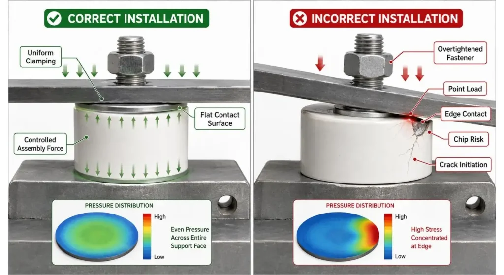
A point of concentration of forces may occur at a sharp metal bracket, washer or overtightened bolt. The damage can manifest itself right away as a chip, or the small crack can propagate and grow under vibration and temperature cycling.
Design and use of controlled contact surfaces, appropriate radii and washers or compliant interfaces as needed. Don't force a ceramic part to make up for the alignment of other metal work.
An alumina ceramic spacer has the advantage of being simpler than a thin, complex insulator with multiple "accordion loads," where the use of the isolator is to define a gap. In fact, according to ProuPCERA, these spacers offer both electrical isolation and structural positioning.
| Design Input | What to Confirm | Risk if Missing |
| Electrical duty | AC/DC voltage, frequency and transients | Insufficient insulation design |
| Conductor layout | Position, size and electrical potential | Inadequate separation |
| Creepage and clearance | Surface and air paths | Tracking or flashover |
| Hole geometry | Diameter, position and ceramic web thickness | Weak walls or poor wire routing |
| Mechanical mounting | Clamp surface, fastener and assembly force | Chipping or hidden cracking |
| Thermal condition | Temperature range and cycling rate | Expansion-related stress |
| Environment | Humidity, dust, chemicals and vacuum | Surface leakage or contamination |
| Ceramic grade | Alumina purity and required performance | Unnecessary cost or unsuitable material |
| Inspection | Dimensions, appearance and dielectric testing | Uncontrolled acceptance |
| Assembly validation | Final housing, conductors and fasteners | Component passes but system fails |
Let Ceramic and Metal Flows Naturally
When it comes to assembly, room temperature is not considered a high temperature fit.
Metal terminal, housing and fasteners have expansion rates that may not match that of alumina. As the equipment heats up, a tightly constrained ceramic component could thus be subjected to an increasing stress, followed by another stress pattern when the equipment is cooled.
Confirm operating temp, heating rate, cooling rate and number of cycles. Provide sufficient position control to keep ceramic free from positional lock up between expanding metal components.
An alumina ceramic tube can be used to create a continuous insulating sleeve in conductor or sensor protection in a hot zone. Despite this, there is a need for its wall thickness, unsupported length and end support to conform to the thermal and mechanical environment.
Click on Purity in the Application box.
Not all the highest alumina percentage is the best commercial specification available.
Grade of material may affect the electrical properties, thermal stability, mechanical properties, surface finish and machineability and machine cost. The selection is based on voltage, temperature, atmosphere, sensitivity to dirt and dimensional constraints.
Avoid using purity requirements instead of performance requirements. Indicate the survival of the isolator and the verification to be done.
Holes, grooves, steps or mounting features can be customized to meet the requirements of the application and are available for review from ProuPCERA's drawing. The quotation should clearly distinguish the critical insulation surfaces from those surfaces that may only require normal manufacturing control.
Give a check for Surfaces Electricity Can Reach
A dimensional report could verify the diameter and the location of the hole and not the one most critical to insulation.
Look for chips, cracks, sharp edges, grinding marks, contamination and conductive residues on the working surfaces. Closely monitor narrow ceramic webs, hole exits, clamping areas and surfaces that are between varying electrical potentials.
Methods of short-time electric-strength testing of solid insulating materials are given in IEC 60243-1, which include methods associated with surface breakdown. Material test results should not be equated with the approval of the finished geometry of equipment.
Prior to the production, agree on whether or not the Dielectric Testing, Dimension Testing, Appearance testing or Batch Sampling is needed.
Complete Assembly, validate.
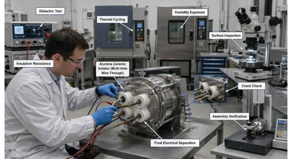
It is not possible to replicate metal interfaces, wiring, contamination and heat in the finished product with a loose ceramic isolator.
Test typical assemblies with production conductors, fasteners and houseings. Where relevant, add in the necessary voltage condition, temp. cycling, contamination/humidity exposure and mechanical vibration.
Following testing check for:
- surface tracking;
- flashover evidence;
- Any crack or edge chip;
- loosened conductors;
- reduced clearances;
- discoloration or deposits;
- Modifies the arrangement of points.
It is not a question of just demonstrating alumina insulation. To demonstrate that the finished design provides sufficient separation between the conductive components during a life cycle.
Conclusion
An alumina ceramic isolator is effective in providing the same electrical boundary protection by its material, shape and installation.
First, voltage and the location of the conductors. Then look at creepage, clearance, spacing of holes, clamping and thermal movement and surface condition. However, even a high purity ceramic part does not overcome the problem of an uncontrolled leak path or a mounting detail which gradually harms the part.
Include a drawing, conductor map, operating voltage, temperature requirements, mechanical loading, environment and inspection requirements to be sent to the supplier. That information gives a more dependable isolator than the information “high grade alumina” by itself.
FAQs
Q1. The alumina ceramic insulator is what?
An alumina part to separate and support conductive parts. It can also serve as a heat resistant, positioning and mechanical support.
Q2. What is the difference between an insulator and an Isolator?
The terms are used in a similar way when it comes to sourcing ceramic components. In an electrical system, “isolator” can also refer to a disconnecting device and it is important to specify the drawing and application.
Q3. Is alumina ceramic suitable to be used at high temperatures?
Alumina has many applications in high-temperature electrical applications. It will depend upon the temperature cycle, atmosphere, mounting stress and material grade.
Q4. Why crack occurs in ceramic isolators during assembly?
The most common causes are different clamping, impact, misaligned clamping, sharp metal contact and mismatch of the thermal expansion. The mounting design should not have any concentrated stress.
Q5. What do you need to know to figure out a quotation?
Material Grade, Drawing, Voltage, Hole Layout, Conductor Size, Temperature, Mounting Method, Critical Dimensions, Quantity and Inspection Requirements.


In This Article
- 1 Clearly articulate What the Isolator Must Separate
- 2 Bulk Insulation is One Barrier of Many
- 3 If you're using Multi-Hole Geometry, you will need a Conductor Map
- 4 Keep Edges Proximate to the Assembly Free of Damage
- 5 Let Ceramic and Metal Flows Naturally
- 6 Click on Purity in the Application box.
- 7 Give a check for Surfaces Electricity Can Reach
- 8 Complete Assembly, validate.
